
|
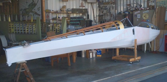
After all that work fitting everything to
the fuselage it all came off for cleanup and painting, just like you
see in the car buildout TV series. The fuselage went to a powder
coat shop for the application of a two-part, baked on polyurethane
coating
that will provide the basis for attaching the fabric. Gray was
chosen as the color since it is much cooler than the black and would
blend in better with the rest of the items in the cockpit
area. (Note: You may
need to shop around to find a company that has a large enough oven to
handle the 20' fuselage. Some auto painting companies might have it. Also prices vary so it may be worth it
if
you are controlling costs.)
|

|
Although
this shot is a little further in the process, it shows that the carry
thru plates were also given the polyurethane paint except for the
inside. If you look at the right hand side of the front plate you
will
see the bare aluminum with some remnants of zinc chromate from over
the
years. The tolerances between the wing spar and the carry thru
are very close and even a "thin" coating of primer or zinc chromate may
be too much to allow for easy mating of the wings to the
fuselage. Once you have everything bolted together and rigged is
not the time to find out that the wings won't go into the slot.
They would be extremely difficult to strip without completely removing
them. At the bottom you can see the spoiler/brake bell crank
has been installed as has the brake shoe. On the left of the
photo you can see one of the older Teflon cable guides that don't show
a significant amount of wear from over 1,500 hours of flying. If
you have to make new ones, it doesn't take any longer to make them from
Teflon or Delron and I think it is quieter of the long run. I was
missing about 8 of them so borrowed a friends small lathe, purchsured
some Delron from the plastics store and went to work. I made a
couple of extras just in case once I got started and found it wasn't
all that hard.
|


|
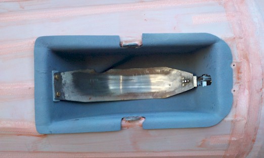
The skid was an interesting project that went through a couple of
iterations. Harry had provided a laminated blank with the curve
already built in, however, it was going to be heavy even after
trimming. My son and I tried for a couple of hours to fit it to
the fuselage and finally gave up.
I ordered a skid from K & L
Soaring with the holes already drilled. The only problem was that
dad didn't get all the attachment points forward of the cockpit
bulkhead in exactly the same positions. So we plugged the holes
with epoxy and dowels and went back through the fitting routine.
We started by bolting the front
two holes then putting the number of rubber blocks in each
position. The rear of the skid was then forced down onto the rear
blocks and clamped in place. Once everything was properly aligned
we used a long drill to come up through the fuselage bracket, blocks
and then the skid. This assured the proper angle for the
holes.
After everything was bolted in
place I spent some time keeping the wood fully saturated with water,
although a blend of ammonia and water would have been more
effective. I left it bolted up until the wood was completely dry
and ended up with the requisite curve without building a mold as shown
in the restoration manual. It was then sanded and sprayed with
multiple coats of a high quality spar varnish.
I went to a local sheet metal
company near the airport and had them use their shear break to cut the
metal skid plate to the specifications on the drawings. I drilled
and countersunk holes for the wood screws but could convert them to
bolts is the screws don't stay in place with use which hasn't been a problem so far. I also
have several weld beads put across the surface to help with braking
ability when landing on asphalt surfaces, which is what was on the old
plate. These will be redone as they wear down.
|


|
This was the tough one. If
you don't need to remove the cockpit skin, then don't. This is
the second time around for this one, which made the alignment a little
more tricky. The top image is the beginning point with C-clamps
doing the major holding in place job. As I noted before there is
a lot of pressure that the cleckos can't handle unless almost all the
holes have one.
The middle image shows how many
cleckos it takes and the plans talk about needing at least 250 cherry
max rivets for the job. You are only looking at one side from the
center line stringer to the cockpit rail so there are lots more cleckos
on the other
side. I was fortunate that we had enough of various sizes to fill
almost all the holes, which was the result of many years of collecting
them from the aircraft company salvage yards in the San Diego area
during the 50s and 60s by my host's father with my dad contributing to
the hangar
supply when he cleaned out our garage. I am sure some of them
were used
during the first restoration.
The bottom image shows the
riveting job almost done. The remaining holes had some variations
in depth so additional rivets had to be ordered, but at this point the
hard parts are done since the cockpit rail rivets are in place.
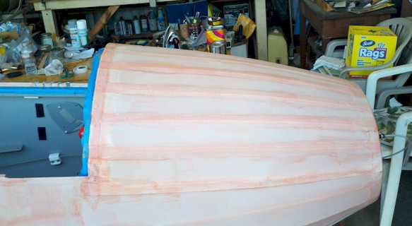
In this picture you can also see
that the wing root fairing is now installed, so everything is moving
along.
|

|
This
picture
shows the progress being made on the cockpit area now that the outer
skin has been installed. At this point the canopy fairing is just
cleckoed in place while the fitting process was underway. While
the front edge is lining up well with the instrument panel hoop, the
rear frame hoop is still not aligning completely with the cockpit
turtle deck section. I tried to be very careful in establishing
the correct position for the turtle deck when riveting the bottom rail
back onto the skin, but it still has to be gently pushed into position
before it drops onto the latching pins.
From this shot you can also
see how the rudder cable guide modification was completed. Now
both sides look exactly the same versus having different
configurations. Essentially I made the old one look like the new
one since it was the governing piece based on the scrap stock I could
get from the plastics store.
|
 |
This
is the
beginning of the nose section buildout. A new bulkhead was built
that includes a small shelf for the Winter mechanical variometer 0.45
liter bottle. It is held in place with a large regular hose
clamp. There is another shelf on the front of the bulkhead but
the Tazman electric variometer turned out to not need one.
The set of three holes on the left
side of the bulkhead are for the pitot and static lines coming from the
nose. The hole above the vent tube will align the total energy
tube that has been routed from the vertical fin through the turtle
deck and under the seat pans to the nose area.
The air vent tube in now in
place. The zip ties at the front end were replaced with a
hose clamp and enough slack left so the nose cone can be taken
off. Don't forget to allow some slack in the static and pitot
lines. I practiced attaching things inside the nose through
the nose cone bulkhead to make sure once the fabric was on I could
still get to each item especially the tow hook.
The long cable along side the hose
is the elevator trim. It has been safety wired to the bulkhead
hoop and secured where it goes through the nose bulkhead. You can
also see the pulley installation for the tow hook release and spoiler/brake cable on the left side.
|


|
Much
further along now with the nose bulkhead getting a coat of epoxy
primer and riveted to the fuselage stringers. The rudder pedals
are now installed and the new springs attached. K & L soaring
had all the necessary springs so I just ordered a full set rather than
trying to find them at various other vendors.
The oxygen bottle has been installed
using a small flat plate of aluminum and adele clamps to attach it to
the fuselage cross members. I can't reach the valve knob
in-flight so have it on my checklist to turn on before takeoff.
The pitot and static lines are
installed and routed to the back of the instrument panel. The
battery pack on the back of the panel is for the Tazman variometer in
an effort to save valuable weight. All the repairs over the years
added to the overall weight so I put the project and me on a diet and
replaced a 12v wet cell with this 9.6v radio control dry
cell from Radio Shack. The only downside is the audio volume will
only operate at
the #3 level vs. at the #5 level that 12v would provide however this
has not been a problem during flight since the 3 setting is just about
right.
The nose fairing tubes are all in
place and the fairing transition pieces held in temporarily. They
were riveted to the nose bulkhead prior to covering. I installed
blind nuts on the bottle hoop so the panel could be easily removed if
it became necessary. The longitudinal tubes
have been safety wired to the bottle hoop through the small holes you
can barely see in the hoop to prevent them from
moving around once the fabric is attached. A little trick passed
along to me was to curl the twisted wire end back on itself so you
don't have any sharp ends that can catch you later when working inside
the nose making connections. If you zoom in on the picture you
can see one example of this on the stringer parallel to the vent tube.
The bottom shot is the wing
fitting to check the aileron and spoiler rigging. Since I didn't
change any of the settings on the bell cranks and cables I didn't
expect any problems. We had to add a couple of washers to the
bolts in the stick stops to keep the ailerons within the limits, but
that was an unknown since the original stop bolts had been removed
years
ago. We weren't too far off. The right spoiler required two
turns on the attachment fitting to make it match the left
deployment. The difference wasn't enough to cause an adverse
roll, but I just wanted everything right. The gray on the ribs is
epoxy primer to cover spots where the chromate had come off over the
years.
|


|
The
instrument locations have been finalized (yes there is an extra
airspeed indicator in the lower hole but it is just filling in for the
Winter variometer that I had to order). The layout allows for
being able to see the airspeed needle and the electric variometer
readings with a simple glance inside.
The mount on the lower right is
for the Icom handheld radio and is designed so it is held in place with
the standard belt clip. This makes it easy to put in and take
out. The antenna cable goes under the floor boards to a point in
the wing bay where it is attached to the handheld radio antenna inside
the fuselage. This eliminated the external antenna and for the
type of flying on plan on doing will be adequate from a range
standpoint. So far in the air reception has been excellent but I
haven't done a transmission yet to determine if there is any
interference from the fuselage skins.
The black box on the left side is
the Mountain High oxygen controller that replaces those big bulky WW II
constant flow regulators. I elected to get a medium size aluminum
bottle to save weight but still give me plenty of use time for the type
of flying I will be doing. You can see the bottle mounting plate in
this shot. In the bottom photo you can see the red oxygen feed
line under the left longeron. I held it in place with some left
over decorative electrical wire cover that already has a sticky backing.
A quick note on the knobs.
You want to keep them off the panel so you can get your fingers behind
them to pull. I found that automobile air-conditioning hose works
great since the inside diameter is just the right size and is very
rigid. I got some for free from a local auto shop. I was
being teased about the yellow stripe around the red tow release know,
but I have since found an old slide with my dad's hand on the stick and
the yellow stripe.
The plate on the carry thru shows the original contruction date and weights from 1958.
|
|
Here
are some shots of the instrument panel after completing the wrinkle
painting and installation of the final instruments. I like the
wrinkle look but it took time and some Internet searching to finally
find a brand of paint and local location to buy it. If you are
interested in doing this go to your neighborhood Auto Zone store and
ask for VHT wrinkle paint in a spray can. Other auto store may
also carry it but Auto Zone was the only one that showed up in my
searches.
I applied four coats but I found
that probably only two heavy coats would be enough when I did the
sizing ring on the Tazman electric variometer. I also did two
coats on a Stearman panel for a friend and it came up just as good.
The instruments are a mix of old
and new with a Schweizer airspeed indicator, a surplus Air Force
altimeter that was donated to the project by a friend, the original compass and g-meter from the 1963 rebuild, then
the new Tazman and Winter variometers. I also installed the
standard Schweizer fresh air vent sine it looked much neater than the
home made version my dad had installed years ago. The only thing
missing is the data plate that will be installed in the lower right corner after the weight and
balance is completed.
|


|
I
was initially puzzled about these alternate seat belt attachment
fittings. Then I ran across something that indicated they were
some type of kit to move the point forward from the original point you
see just behind it. Although I haven't hooked everything up yet,
I am assuming that this allows the lap belt to actually give you more
protection since the angle provided by the new mount wraps tighter
around your waist. The floor pan has been modified to clear the
new bracket.
Here
is a shot of the new seat belts that continue with the color
scheme of gray and maroon from Hooker. I elected the wider lap
belt and narrower shoulder belts for safety and comfort. Based on
the condition and age of the original hardware I also elected for all
new hardware even with the increase in cost. I imagine you can
send Hooker your hardware and have new belts fitted. The shoulder
harness webbing is veed and has plenty of length to reach the
attachment point on the fuselage cross member allowing for
adjustments. I have since removed the sholder harness pads so
there isn't as much bulk to try and move around while putting them on.
|


|
These
shots show the finished and installed aft turtle deck bulkheads and
stringers.
The vertical fin was bolted in so the total energy tubing could be
fitted from the tail up to behind the instrument panel. I used
heavy duty opaque plastic water tubing so it would be stiffer between
the turtle deck bulkheads to minimize flexing that could affect the
readings. I installed a fitting in the line just before it
enters the first bulkhead so the vertical could be removed for covering.
Although it is hard to see in
these
pictures the total energy mounting tube has been welded to a half piece
of aluminum tubing that fits around the leading edge tube. This
was epoxied and riveted to the leading edge and another half piece
glued/riveted to the back side of the leading edge tube. This
created a clean and strong joint since it is essentially a complete
wrap around the leading edge. The actual probe that was donated
by Tom Riley will slide
into the tube with almost enough friction to hold it in place but I am
using a
piece of electrical tape around the joint to make sure. No
problems so far the the Tazman appears to working great with this
arrangement.
|
|
................1...........................2............................3.............................4........................5................6.......................7.
|
In
previous pictures you have seen the canopy framing being held in place
with cleckos and just an empty shell. 1. is the canopy
attachment fairing now completely riveted to the framework. The
canopy is one of the old ones with two big cracks so it worked great
for fitting since I didn't have to worry about breaking it. The
biggest issues were with the fit against the cockpit turtle deck since
the new rear canopy hoop had a slight angle that didn't we didn't get
quite right during the welding. A little pushing and pulling
worked out most of the fitting problems and the front hoop was almost
spot on so didn't require any additional work. Someone reminded
me this glider is 60 years old so things aren't always going to fit
like new. This does help mentally with accepting less than
perfect.
In 2. the
canopy frame process is now moving forward toward finishing after
having spent a hour or so sanding off all the excess
bondo now covering the pop rivet heads. I wanted to keep the
sleek look of having everything flush so I had also done a little bit
of grinding so I wouldn't have to build up bondo to cover them.
You can see I managed to keep the amount of leftover bondo to a
minimum. The inside is painted with a coat of epoxy primer and I
have now sealed all around the frame with clear silicon to help keep
out water and give a good base for the final paint.
3. shows the
frame with the last coat of filler primer
before wet & dry sanding and coat of epoxy primer as the base of
the final paint. I think it looks good and hopefully I won't get
any major cracks in the bondo as the canopy is taken off and put back
on all the time. The paint shop that did the wing striping and
priming of the wing surfaces felt there wouldn't be any problem with
bondo, so only time will tell. So far there haven't been any issues with cracking after several setups and tear downs.
The new canopy (4.) came from
Aircraft
Windshield in Los Alamitos, CA (southern Los Angeles area) (http://www.aircraftwindshield.com/index.html).
They were great to work with since I took an old canopy and the frame
in at 10:30am and picked up the completed new canopy at 2:30pm the same
day. Since I had the frame they offered to drill the mounting
holes at $2 each which was the best insurance against cracking that I
could have purchased since the drilling was on their nickel. 5.
is looking at it from the front, while 6. is a shot through the glass
to show how distortion free it is so I am very pleased. 7. is a
shot of the bubble head nuts I used instead of just plain locks
nuts. I got them through Genuine Aircraft Hardware but they
are a little pricey at about $1.10 each when ordered in the necessary
quantities. (http://www.gen-aircraft-hardware.com/storeintro.asp)
|


..................1.........................................2.........................................3.....................................4.................................5.
|
Starting
with 1. the cockpit turtle deck
after doing the bondo filling and sanding to
cover up the rivets holding the skin to the bulkheads. Most of
the bondo was sanded off but I haven't primed it yet since the area
outlined by the pencil line is going to be cut out (photo 2.) and
Lexan bolted in
its place (photo 3.). That means there are a lot of mounting
holes to drill
and dimple before the cut is actually made. I really like the
look of the extended cockpit area since it helps give the fuselage a
longer look as shown in 4. with the two pieces in their
approximate positions than just having the short canopy area,
especially with
white paint. 5. is the Lexan piece that will be
installed after all the painting is completed. It is drilled and
ready to go except for removing the protective covering. Making
the template for cutting the Lexan was a lot of work but I think it was
well worth the time and effort. I have the template rolled up and
saved just in case I should ever need to make another one.
|

|
This
is a shot of the area under the seat showing the guide block for the
elevator cable as it goes to the back. You will notice the stick
has been chromed, which was one of the neat things my dad did during
the previous rebuild. The tube on the left is the total energy
line coming in from the aft fuselage turtledeck. Be careful that
something like this is not routed where seat pan hold down screws could
pierce the tubing. I rerouted this slightly and also used it to
help support the radio antenna extension cable into the wing carry
through area. Although not done at this time, all the seams from
the longerons down have been sealed with silicon to keep moisture out
of the joints. Make sure to leave the drain holes open so any
heavy water from an unexpected rain can get out rather than sitting in
the bottom.
|

|
This
was the first fitting of the wheel brake that came with the wheel well
cover I got from a local 1-26 surplus supplier. It has brake shoe
material riveted to it and was somewhat longer than the metal only
brake originally on the glider to help keep out dust and dirt at the
cable entry point. However, I found that there are some
differences between models and/or tires so this later version would not
fit with the shoe material and I had to go back to the original one
that only wraps around the tire providing some friction for
stopping. I also replaced this tire with a new one since the one
pictured had too many sidewall cracks from old age and I didn't want to
risk it giving up on a hard landing. Cheap insurance from my
point of view. See below for more on installing the fiberglass
cover.
|

|
I just like this shot since it makes the fuselage look long and sleak,
especially when you add the nose cone. It also shows how well the
added nose fairing tubes help with giving the nose a more rounded and
smoother look.
|

|
This
was the starting point for my first attempt at putting on the
covering. The elevators were small, easy to handle and had all
straight edges to work with. This was a wrap job around the spar
first attaching the bottom side to the trailing edge and then the top
side with at least the one inch overlap around the trailing edge.
The hardest part was making the straight line cut of the excess fabric
from the top wrap without having the razor "accidentally" cut into the
covering, which would mean an ugly patch. The same problem
presented itself at the ends, but by taking it slowly and getting some
good advice on technique from friends.
|

|
Here
is a shot of the horizontal stabilizer part way through the initial
attachment of the Poly Fiber fabric. This is the method covered
in the Schweizer drawings I got from K&L Soaring where you don't
have to put the hold down strip down the middle of the main spar.
This allowed for an easy wrap. I started by tacking the fabric
along the spar edges to keep it from moving around and then wrapping
the bottom side to the leading edge
tubing with as much overlap as possible. The ribs were prepped
with Poly Tak and then another coat added so the fabric could be worked
into the wet glue and attached without the
screws/rivets, which is allowed in the revised specifications.
Once I got the hang of working around the curves with the iron
the job went quickly but it does take some patience. Once both
sides were covered and the Poly Tak had plenty of time to dry
I did a light shrink, used reducer to make sure the Tak had been drawn
through the cloth
and then let everything set overnight before doing the final shrink.
|
|
|
So
as not to bore everyone with the entire
covering process here are the tail surfaces up through the two coats of
sprayed on Poly Brush over the top of a single brushed on coat.
You can see all tapes over the ribs that were put on with Poly Brush
after the initial brushed on coat and then the edges ironed down where
necessary in between the spray coats. I attached the rudder and
elevators to the main structure with temporary bolts and then installed
the gap strips so they would get the same coverage and give everything
a uniform look after final painting. It was a little tricky
swapping out the bolts for new ANs, but by using the new bolts to push
out the old ones everything stayed in line. The alternate method
would be to install the gap strips
after the silver coats or the final paint, but that also has it down
sides. They now have three coats of silver and have been given an
initial sanding to remove as many of the imperfections left from the
spraying in an airport environment.
|
 
|
I
have now moved on to covering the fuselage which is going to take a
long time since there will be a lot of taping to do after the fabric is
on. The left image is the bottom section the is the starting
point according to the factory covering instructions. This is logical
since it allows for the side piece lap joints to flow downward
which looks better under the final taping. At this point the
wheel well opening has been cut out but the fiberglass wheel cover
still needs to be installed (see below).
The right image shows the right side of the fuselage that still needs
to be covered. The left side piece goes the entire length of the
fuselage from the rear vertical tube to the nose cone ring.
Again, this is the way the original instructions called for covering.
Don't forget to make sure all your
control cables and prooperly run and that all the guide fairings are
wired into oplace since you won't be able to get to them again.
|
|
|
This
top image is the left side with the fabric having been initially
attached to the longerons, the fuselage tub and the root section
support plate. The bottom image is the cockpit tub covering showing how
to get the fabric to lay down on the sheet metal. The edges
around the tub were pre-coated with Poly Tak (silver area vs. red area)
and the rest was given a
coating of Poly Brush (red stuff). The fabric was attached to the
skin edges with a fresh coat of Poly Tak rubbed through the fabric and
allowed time to properly dry. The fabric was then shrunk through
progressive heat levels with
an iron to get rid of as many wrinkles as
possible. Then Acetone was used to draw the Poly Brush up into
the fabric for the final attachment and the irom used to reduce any
bubbles that might have appeared. The same was done with the
root plate. This process has worked extremely well since no new
bubbles appeared during subsequent spray coats.
|

|
This is the
fuselage with all the side covering in place on both sides. At
the front you can see the bottom of the cockpit skin hasn't been
covered yet, but that is now done. Sure looks long, doesn' it?
|
|
Here
is the bottom of the nose before and after covering. This gives
you a good idea of all the fairing tubes that will need to be covered
with 1/4" tape on the peak of the tupe. It is a little
hard to see in the picture, but the fabric had to be split toward the
front of the nose in order to get it to wrap around the compound
curve. I made an initial cut from the nose to the flat area at
the rear of the tow hook slot. I then got everything attached in
the slot which helped remove some of the loose fabric. I then
made another cut to get rid of the excess fabric forward of the slot
and glued it down. This area will be covered with tape on the
underside so I wasn't quite as neat as I probably should have been.
This shot also shows the spacing blocks
between the fuselage bulkheads and the fairing tubes to keep the bows
in them as the fabric is tigthened.
|
|
This
is the
fuselage in the upright position getting ready to put on the top nose
fabric. The sides have now been shrunk to the 300 degree point so
everything looks nice a clean. The wing spar hole has been cut
out and the fabric rolled around and attached on the inside so there
are no raw edges to break loose from the root plate. I had
decided to leave the fabric in place over the large lightening holes so
they didn't need to be trimmed and also rolled inside.
|


........................ .........1.......................................2......................................3.....................................4.
|
1.
is a shot of the nose top before it was
covered and 2. is after the
covering. The fore and aft bulkhead fairings were prepped with Poly Tak
before applying the fabric and then a fresh coat of Tak worked through
the fabric as is was put on. 3. shows that I was able to
get everything wrapped without having to do the compound curve split
that was necessary on the bottom. This was partly due to less
down slope on the nose top than the bottom and the fact that there are
nine fairing tubes to smooth out the curvature. The fabric has
been pre-shrunk at 250 degrees with the next step at 300 degrees and a
final at 325 so as not to deform the fairing tubes. 4. is of the
nose with a the hand applied coating of Poly Brush
and then tapes added to the fairing tubes. I used 1" tape here
since it met the Poly Fiber standards and it allowed for spacing
between the tapes at the narrow front bulkhead points. If I had
used 2" tapes there would have been such a severe overlap point at the
nose bulkhead it
would have been almost like laying on another layer of fabric. It
looks really good this way and allows for mounting the nose cone since
there is no excessive buildup of tapes.
|


.................... ........1........................................2........................................3.......................................4.
|
This is a series of images on the wheel
well cover installation. 1. is the rough fitting of
the cover with the brake shoe in place. The cover didn't fit very
well over the tubing forming the well and was going to be a messy taping job. One of my advisors suggested
some areas that could be trimmed and then to use a heat gun to reshape
the curvature of the fore/aft sides so they conformed with the fuselage
tubing better (photo 2.). Using a heavy glove I was able to
soften the
fiberglass and then put the cover in the well and hold the edge around
the tubing until it rehardened. It also required a little forming
work on the rear edge to get the best fit. 3. shows
it installed with 4" pinking tape as noted in the restoration
manual. 4. is the completed installation with the
coating of Poly Brush and the pinked edges ironed back down.
|

    
1.
2.
3.
4.
5.
6.
|
This
is the current point of covering the fuselage. Image #1 is
the vertical fin
with rudder attached due to the gap cover having been permanently
installed. The elevator cables have been strung through the
vertical spar and bolted/safetied to the control horn and the elevator
push rod installed permanently while there is an opening and the
ability to work in this narrow space. The rudder cables have been
temporarily attached and a template can made to locate where
they will come through the fabric so the slot can be cut in the correct
place when the time comes.
Image #2 is the rough fit of the fabric to make sure there is enough
all around for the gluing. Image #3 is the is the fabric now
attached to the fuselage and the initial shrinking done at 250
degrees. Again the front fairing was given a prep coat of TAK and
then a fresh coat worked through the fabric. Image #4 shows the
covering ready for taping with the
final shrinking done at 325 degrees. I did progressive shrinkings
to make sure the stringer structure was not going to bow under the
pressure. Image #5 is the fuselage now ready for spraying on two
coats of Poly Brush to start the fabric filling process. The coat
on there now is hand brushed before the taping which can be seen as the
darker areas along the stringers and longerons.
Image #6 is the area around the base do the vertical fin. Either
my father or Harry made up a set of transition fairings that are bolted
to the center stringer just in front of the fin. They provide the
desired angle for the fabric to come off of the fin and go to the
longeron. Tape was then applied on the fin and turtle deck fabric
to smooth everything out. The blue tape was used to keep the Poly
Brush used for taping from destroying any more of the silver coating
than necessary. Everything above the blue tape will be masked off
to prevent overspray when doing the Poly Brush spraying. The area
where the horizontal will sit is eventually going to be covered to keep
dust, dirt and critters out when the horizontal is not in place.
It has to stay open for now so the rudder cables that are tied to one
of the vertical fuselage supports can be released and fished through
the
slots in the fabric. You can see the pencil marked area just
above the inspection plate hole indicator that corresponds to the
template made earlier. The inspection rings have now been glued
on and covered with tape.
|
|
Something
that didn't come with the turtle deck lumber was a small bulkhead for
attaching the aft most part of the fabric. I was puzzled on how
to finish the fabric attachment until I happen to notice it
on one of the drawings and after some experimentation with the
transition fairings decided it was worth building one. It is 1"
high in the middle to avoid interference with lower hinge bolt nut
and safety pin. A french curve came in handy for forming the
shape. It is attached to a bracket using two countersunk AN3
bolts through the drilled holes. It is hard to see but I also
added a small piece of
aluminum extending aft under the bulkhead so there is a fabric attach
point for covering the opening that is normally under the
horizontal. This will keep dirt and other stuff out of the
fuselage when the horizontal is not installed. After it was
installed and covered with fabric it was discovered the bulkhead was
about 3/8 to 1/4 inch too deep, which until corrected will prevent the
horizontal from lining up with the bolt holes. I had to remove
the fabric, cut off about 3/16th leaving a little wood for the bolts,
trial fitted it witih the hornizontal and then reinstalled and covered
it. You can see the results in the lower image.
|

|
Here
is the fuselage with two coats of silver but still needing one more to
provide the necessary UV protection for the fabric. The
horizontal is on during the trial fit for the revised bulkhead noted
above. The masking and plastic has come off so everything can get
the third coat at the same time. I did the third coat on the
horizontal and elevators when I did the right wing aileron cap seal
taps as covered in the fuselage rebuild section of this site.
|
|
Here
are a series of shots taken in mid-October when everything was
temporarily put together for a trial weight and balance. At this
point it is now ready for the final paint job but the local weather and
a backlog at the paint shop have slowed this down considerably.
It is anticipated the painting might get done the week of Christmas if
the weather holds.
|
|
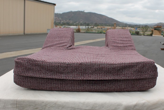
Here
is what the final cockpit interior looks like with the seat cushion,
seat back and stick boot all in position. The thigh pad elevation
is 7" and provides just the right amount of support for longer
flights. I had this built by a professional aircraft interior
fabricator and had him install zippers so the outer covering can be
washed periodically, especially after summer days of sitting in a hot
cockpit waiting for the tow plane. The boot is riveted to the
frame using a washer on the back side for the rivet mushroom for plenty
of support so the leather won't pull away. The frame is then held
to the floor pan with 4 sheet metal screws. The boot in installed
by slipping it over the stick inside out, a tie wrap put around it just
below the top and then the boot folder over into the normal
position. This keeps the boot tight on the stick so dirt and
other things can't fall through.
|
Click HERE to bring up the final preparations and first flight page.
|


 ...
...


